
Progress
This page is meant to be a “book history” of AIRobots presenting sketchy
information about technical progress achieved during the project.
**** August 2012-January 2013 ****
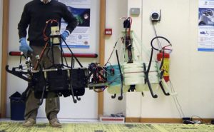
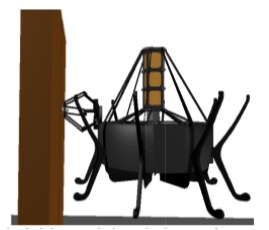
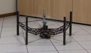
– Ducted-fan prototype: modular configuration
– As a final improvement to the ducted-fan prototype, a modular planar configuration has been obtained by combining two different single ducted-fan aerial vehicles. The obtained final prototype shows the advantages of modular design in term of
- payload: the final modular ducted-fan prototype is now suitable to carry both the manipulator and the cameras in a single vehicle;
- dynamical behavior of the system: the final modular ducted-fan prototype has been designed to achieve full-actuation of the longitudinal dynamics so as to improve the manipulation and physical interaction capabilities.
– To take advantage of such innovative features, suitable control and control allocation algorithms have been designed and tested in both free-flight and physical interaction scenarios aiming at simulating the experiments to be achieved on the final demo by means of the mockup.
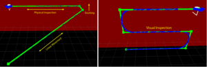
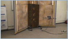
– Final demo: ducted-fan prototype experiments
– During the 3rd IW, the experiments to be achieved with the modular ducted-fan prototype have been planned with all partners to show the effectiveness of the prototype in a real inspection scenarios employing the mockup environment.
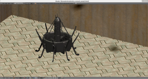
– Simulation environment final updates
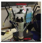
– The accuracy of the aerodynamic model of the final ducted-fan prototype has been updated to take into account for all the main aerodynamic effects measured on a load-cell. The dynamics of the final modular ducted-fan configuration has been included.
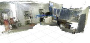
– Environment awareness
– Development and test of a wall identification module suitable to be employed by the high-level supervisory control for an autonomous wall inspection task.
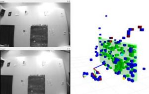
– Development and integration of a monocular visual odometry based on PTAM.
– Development of a dense environment reconstruction module based on a RGBD camera and integration with a monocular visual odometry.
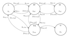
– Task formulation and supervisory control
– Inclusion of motion trajectory for Aerial Manipulation in Primitive Supervisor.
– Integration with High-level Supervisory control and lower levels as for Aerial Manipulator added functionalities.
– Test of communication protocols for the activation of docking operative mode.
– Primitive supervisor now generates trajectories also keeping orientation tangent to assigned path for position.
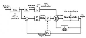
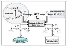
– The high-level and low-level supervisory system have been extended to monitor and control the areal manipulation activities.
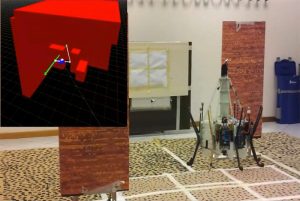
– We extended the high-level and low-level supervisory system in order to enable inspection and docking operations. The extended system was then tested in a simulated environment.
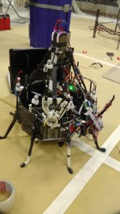
– During IW3 we integrated and tested the overall system in the ETH arena.
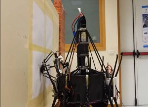
– We tested replanning and inspection tasks using the ETH quadrotor as a test-bed. The areal manipulation system was implemented and tested on the Bologna robotic platform.
**** March 2012-July 2012 ****
– AIRobots Industrial Day in Bologna – UAVs in Perspective
– The meeting has focused on the theme of Unmanned Aerial Vehicles, with a specic attention to future scenarios related to the used technologies, possible civil applications and funding opportunities in future European programs.
– Simulator and virtual environment
– Advanced version of the simulation software and environment with improved modeling of contacts and force sensors.
– Supervisory Control, Task Planner and Teleoperation Algorithms
– Improved integration with the low-level controller and flight tests.
– Prototypes improvements
– Intensive flight tests integrating advanced low-level and high-level funtionalities.
– Docking and aerial robotics experiments to demonstrate general purpose aerial service robotics capabilities.
**** November 2011-February 2012 ****
– Prototype itegration and low level sensors improvement
– 9DOF IMU with three-axis gyros, three-axis accelerometers and three-axis magnetometer with onboard attitude reconstruction;
– Simulator and virtual environment
– First released version of the simulation software and environment;
– Free flight and docking capabilities and manipulator integration;
– Task planning and trajectory testing;
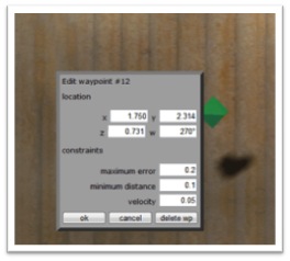
– Waypoints marking;
– Task Planner and Supervisory control
– Path Following: Waypoints exchange protocol;
– Controller design for the robotic arm system:
– Testing and benchmarking of the manipulator in flight;
– Haptic teleoperation algorithms:
– Remote Haptic teleoperation;
– Preliminar force-feedback setup;
– Prototypes improvement
– Intensive Flight tests and integration.
**** July-October 2011 ****
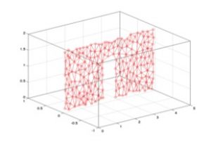
– 3D Environment Reconstruction
– Target Plane Detection from sequences of 3D points;
– Fast Environment Reconstruction by planes detection;
– Convex Surface reconstruction by Self Organizing Maps;
– Denser Environment Reconstruction (Goal: Increase density of sparse pointclouds
in poorly textured environments. It does not run at frame rate);
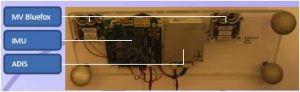
– New Sensor Rig Prototype (MV Bluefox CMOS Cameras (HDR), ADIS16375 Accelerometer & Gyros).
– Task Planner and Supervisory control
– Task Planner: Integration of task planner and user interface. Design and development of task-replanning strategies due to plan failures or user interventions (task abort, task suspension, task replanning);
– Path Planner: Integration of path relanning and task replanning. Development of time-dependent path replanning/recovery strategies (brake, escape, replan);
– Plan Supervisor: Integration of path replanning, task replanning, and trajectory replanning.
Plan/execution tests in a simulated environment considering task/path/trajectory plannig/replanning.
– Controller design for the robotic arm system:
– Joint level position controller has been designed and practically realized;
– Preliminary Joint level impedance controller has been designed and practically realized;
– Integration of the robot arm controller in the overall Software architecture.
– Haptic teleoperation algorithms:
– Multi-dimensional haptic teleoperation using the virtual slave concept;
– Haptic teleoperation using kinetic scrolling mapping;
– Switching based variable scale mapping and haptic telecontrol of aerial robots;
– Vision based haptic teleoperation of aerial vehicles for obstacle avoidance and target approach.
– Prototypes improvement
– Coaxial rotorcraft and ducted fan developments/improvements (aero-mechanical design, robustified drive train, tactile docking modules);
– Robot arm installation onboard;
– Modeling and control (Hybrid modeling, nonlinear control development, impedance control, robust control docking
algorithms);
– Flight tests.
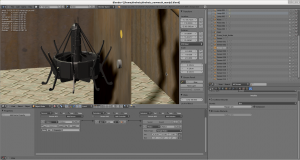
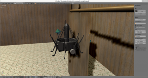
– Simulator
– Integration of a preliminary version of the simulator (Blender) with the existing Simulink low-level controller;
– Simulation of aerodynamic effects;
– Integration with the on-board controller;
– Implementation of force-sensors;
– Preliminary force-feedback to haptic devices;
– Modeling of realistic usage scenarios (Boiler shape and textures, CASY Flight-test room) ;
– Preliminary integration with the task formulation engine.
**** April-June 2011 ****
– Prototypes and flight tests
– Improved layout of the ducted-fan and coaxial considering the hardware to be installed for the second IW (Atom Board
IMU (ST iNemo V2), Arduino (PlugDuino) / Pololu / Xbee from previous Version 1, stereo cameras);
– Flight tests: improved hovering performances, design of a more advanced Simulink controller for the Optitrack lab(available on the internal AIRobots SVN);
– Development of a more advanced testbed at ETHZ and accurate identification of relevant subsystems dynamics for the ducted-fan and coaxial;
– Design and construction of a manipulator system for aerial service robotics (the first prototype of the manipulator with Delta structure has been designed and constructed; the manipulator has been integrated and preliminary experimental tests were conducted);
– Ground station. A ground station consisting of all the necessary equipments has been set up. Very preliminary flying experiments have been conducted Software integration of the complete system has been started.
– Software framework
– Common Software Infrastructure: added repository AR-CAD for sharing the CAD layout of the Stereo Head and future common mechanical components, added repository AIRobots-Software for sharing the Linux Virtual Machine with Real Time Extensions for common on-board software development;
– On-board Software:
prepared a Linux (Ubuntu) RTAI installation for the Atom Board to execute the real-time code developed with the Linux Virtual Machine; first tentative class diagram and specifications of the basic low-level controller to be integrated with high level functionalities.
– Sensor fusion
– Flight tests for motion estimation: flights in close proximity to the boiler surface;
Illumination carried on-board;
– Vision based obstacle avoidance through haptic feedback (Image acquisition from onboard camera;
Image processing to estimate the distance of the UAV from an obstacle;
Repulsive force for each obstacle point detected with in a sphere of a certain radius).
– Incremental clustering for 3D environment reconstruction. Procedure divided in 3 phases:
1. Cluster points in 2D sub-spaces (planes);
2. Find principal direction of each plane;
3. Merge previous clusters with current data.
– Visual Odometry Module Tests
– Task formulation
– Control Architecture (specification of task and path replanning protocols).
– Task Planner (Definition of macro-action models (states and transitions); Specification of a simple user-interaction interface; Specification of task-replanning strategies; Implementation of a task decomposition system).
– Path Planner (Definition and implementation of path replanning and recovery strategies; Specification of RRT path-planning parameters (variable tolerances) for the free flight mode).
**** January-March 2011 ****
– Modeling of aerial configurations
– Aerodynamic modeling and experimental investigation of the ducted fan (experimental measures of the aerodynamic forces generated by each control vane)
– Design of control allocation policies to obtain the desired control wrench vector for the ducted fan
– Analysis of the main advantages of modular configurations for ducted fan
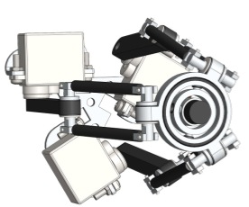
– First approach for physical model of the coaxial prototype
– Derivation of simplified model for identification and control in progress
– Sensor fusion
– Optical Flow based navigation control
– Comparison between the Unscented Kalman Filter and the Extended Kalman Filter using as a reference the Optitrack attitude
– Fusion of Vision and IMU for scale factor estimation
– Control
– Definition of the general control architecture (hybrid automaton to collect possibly different operative modes, path-following perspective for reference generation)
– Development of preliminary control laws (free flight and vertical interaction)
– Task formulation and supervisory control
– Port-based bilateral teleoperation of underactuated Aerial Vehicles
– Preliminary definition of the simulator environment
– Analysis and validation of existing open-source simulator environments: Blender-based frameworks (MORSE, OROCOS)
– Realization of a first benchmark to evaluate the performances of existing open-source tools
– Manipulator
– Investigation of manipulator structures for inspection UAVs
– Manipulator with delta structure was chosen
– The manipulator was designed and preliminary simulations tests were conducted
**** October-December 2010 ****
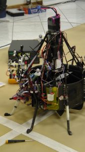
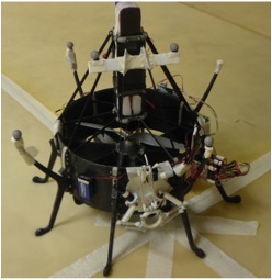
– Mechanical design and construction
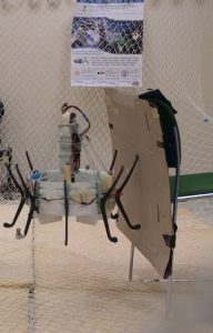
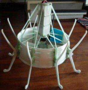
– The construction of the first prototype of the coaxial configuration has been completed and first flights have been carried out (see pictures below).
– The ducted-fan first prototype has been improved
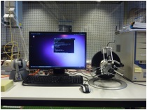
– Software and Hardware
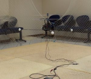
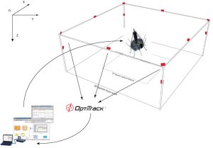
– The software-hardware architecture for the first Integration Week has been realized and tested. In particular the message oriented software framework has been integrated with the low level controller in order to control both the ducted-fan and the coaxial rotor UAVs in the “Optitrack laboratory”. The following components have been integrated
. Low-level nonlinear control law
. Optitrack system to collect the position and orientation of the vehicle (see picture below)
. Joystick stick position and buttons to generate references for the low level controller
. Usb cameras for stereo vision
. IMU acquisition for comparison with Optitrack values
– Flight tests
First flight tests of the ducted-fan and coaxial aerial vehicles have been obtained showing how the framework succeeds in stabilizing the aerial vehicles using the feedback from the Optitrack camera system. During the first Integration Week the performances of the controller have been evaluated collecting several telemetry data. Preliminary flights in contact with the environment have been carried out (see picture below).
**** July-September 2010 ****
– Mechanical design and construction.
– The construction of the first prototype of the ducted-fan configuration has been completed (see picture).
A few features of the constructed prototype are the following:
BLDC motor: Scorpion S-3020-1110KV , 850 W;
Propeller: diameter: 11 inches, pitch: 5.5 inches;
LiPo Batteries: Topfuel 5S 3600 mAh;
Maximum thrust: 3.00 Kg;
Overall weight: 1.6 Kg without payload;
Maximum payload: 300-350 g;
Endurance: 5-8 min;
– The design of the first prototype of the coaxial rotorcraft configuration has been completed and all the parts are in production. A few features of the prototype under construction are the following:
Motor: Scorpion HKII-2221-6 (4400 rpm/V, 525 W, 81 g);
Motor Controller: Scorpion Commander 26 V 60 A ESC (65 g);
Batteries: Thunder Power 5000 mAh 3S LiPo (20C/40C, 363 g);
Total system mass about 1.7kg, with functional payload (about 230 g);
2 x FireFly MV camera with 70deg optics pointing forward;
1 x FireFly MV camera with 130deg optics pointing down;
Expected endurance with full payload about 7-8 min;
– Control architecture.
The overall control architecture has been further developed with the following implemented features:
– Control through Optitrack: rigid body state over UDP network
– Control through Joystick: real time generation of the references control inputs
– Remote control from Simulink using Zigbee or serial cable
– Rapid prototyping architecture: running tests on real time data acquisition and processing using Matlab
– Visual low level stabilization algorithms under development. Two different strategies under test: 1) SURF-KNN-RANSAC, 2) HARRIS-OPTICAL FLOW-RANSAC
– Sensor fusion. First algorithms for GPS/INS/Camera Fusion have been developed.
– IMU / filter design: first running AHRS (Attitude and Heading Reference System) code based on EKF (Extended Kalman Filter)
– Filter implementation based on EKF
– Fusion of IMU and 1-3 cameras output values for position and orientation estimation
– Tests using Matlab/simulink have been done with realistic noises on measurements
– A C++ implementation on a real system is in progress.
**** May-June 2010 ****
– Definition of operative scenarios. Industrial scenarios have been fully characterized (deliverable D2.2) and the main features of meaningful applicative fields have been extracted. A set of representative tasks has been identified and a representative mock-up environment has been sketched.
– Laboratory set-ups and activities.
– The Optitrack Camera System by Natural Point has been fully installed:
preliminary successful experiments of hover flight with a previous prototype of
ducted-fan MAV with position and orientation acquired via Optitrack;
preliminary estimation of delay / sample rate and precision of the cameras.
– Labs equipped with Rotor/Rotorcraft test bench with Safety Casing Measure;
– An exhaustive state-of-the-art research about GPS/INS/Camera Fusi
on have been done;
– Preliminary simulative tests for dynamics sensor data integration have been achieved;
– Preliminary discussions and researches about the control architecture and logic have been done;
– Mechanical configurations.
– For both the aerial configurations (ducted fan and coaxial rotorcraft) the first prototype design has been completed.
– FEM optimization of airframes: load cases defined by crashes and free flight with the objective of minimizing weight and maximizing robustness.
– Construction of the prototypes is ongoing (stamps for fiberglass parts of the fuselage / structure).
– Hardware.
The overall Hw architecture has been further developed:
– An I/O concentrator based on Arduino MEGA has been finalized (first working version).
– The high-level electronics has been further developed with integration of IMU & low-level sensor.
– Several sensors hsve been tested for possible implementation on the first prototypes:
-> Proximity sensors;
-> Current and voltage sensors;
-> Switches (contact detection);
-> Ultrasonic Obstacle Avoidance Sensor specifically developed for AIRobots;
**** February-April 2010 ****
– Laboratories set-up. All the partners set up dedicated lab facilities for the activities of the project. The Optitrack Camera System by Natural Point to assist real time tracking of the aerial vehicle have been also installed in a lab.
– Electronics Development. Preliminary Hw/Sw development and integration have been achieved. The overall Hw architecture has been structured on three layers: the low level, dedicated to basic inputs/outputs and sensors, the mid level, on which low level control and estimation algorithms can be implemented, and the higher level, meant to execute different high-level control tasks.
Low-level electronics. The lowest level integrates low level sensors as well as low level processors. First attempts have been devoted to:
– improved I/O specifications for the low-level hardware to meet the expected requirements of the first two prototypes;
– integration of low level sensors, in particular custom IMU, with the mid level hardware;
– design of open-source code for an off-the-shelf IMU;
– use of the open source software and hardware platform Arduino to implement low level processing units;
– integration of a low-level communication based upon Zigbee 802.15.4 protocol within low-level and mid-level hardware.
Mid-level electronics. The mid level relies upon a TMS320F28335 IC suitable to design both advanced control algorithms and to integrate a large number of I/O to govern actuators and to read sensors. First attempts have been devoted to:
– integration of the TMS board within the Simulink environment in order to design mid-level control and estimation algorithms directly in Matlab;
– design of custom boards to integrate the TMS within the first prototypes.
High-level electronics. Possible high-level hardware architectures have been considered. In particular miniature boards based upon Atom Z processor which allows to run multi-tasking operative systems and to integrate high-bandwidth wireless communication.
– Mechanics. A deep state-of-the-art about existing technologies and aerial configurations have been developed.
Final industrial scenarios and benchmarks have been better characterized and detailed.
Preliminary designs and sizing of the two aerial configurations have been done and first construction phases organized.
**** February 2010 ****
Kick-off meeting.